Microprocessor Based Traffic Controller using 8085 Microprocessor
 The project involves traffic control circuit using 8085 microprocessor. Through
software traffic of North-East-West-South can be controlled. In project traffic
lights are LED’s,connected to 8085 microprocessor with PPI (Programmable Peripheral
Interface) 8255 and buffers. LAMPS can also be used instead of LEDs but those are
to be driven by relays & transistorized circuit.
The project involves traffic control circuit using 8085 microprocessor. Through
software traffic of North-East-West-South can be controlled. In project traffic
lights are LED’s,connected to 8085 microprocessor with PPI (Programmable Peripheral
Interface) 8255 and buffers. LAMPS can also be used instead of LEDs but those are
to be driven by relays & transistorized circuit.
The ON time duration of LEDs can be observed. For this, seven segment displays is
connected in one of the port of IC 8255 PPI and its indication or counting is synchronized
with ON time of individual LEDs of the signal. In actual practice the light and
its timings (ON & OFF), its displays are controlled individually for all roads (4-direction)
by microcontroller.
Here a model of traffic controller is prepared that gives general idea about how
Red, Green and yellow lights can be controlled. It also helps to study the interfacing
circuits with 8085 microprocessor. 8085 microprocessor can be mapped as memory mapped
and I/O mapped. This project involves study of I/O mapped interfacing.
In I/O mapping, I/P or O/P devices are connected through 8255 PPI which has three
ports. In this project two ports are involved, to port A indicating LEDs are connected
and to port B seven segments are connected. Since no external memory is to be interfaced,
memory mapped interfacing scheme is not used. By giving suitable control word each
port can be initialized & hence can be programmed to give desired output. As 8085
microprocessor kit used, programming is done in RAM and program is in assembly language.
About working of Project
We have used 8255’s port to carry out respective functions i.e. traffic controller, just the difference is to change the addresses of port and control word via programming. When we start programming, we can initialize all ports, by providing their respective addresses. If we are using U25, 03 is the control word address and if it is U26, 0B is the control word address. Then after we can write program to turn on LEDs and 7-segment with their respective delays on desired ports. 8085 KIT provides monitor utilities to do specific task in our software programs. Monitor utilities program starts from memory location C000 to c0FF. In traffic controller, programming, we have called an instruction for providing delay from memory location 0615, which provides a delay of = [35 * DE +111] * 0.586 micro sec [3.57MHz]. After 69FF, our original program starts from RAM memory location C000 onwards.
Preferred Technologies
8085 Microprocessor Based Programming and Circuitary
8085 Includes
In 8085 kit RAM location starts from 7000 up to 128 byte. Hence the limitation of program length is up to 128 byte. Turn on display RED, GREEN and YELLOW light in synchronism with the display the length of the program is 37 byte. But the digit display is single digit. Max delay that can be provided is of 9 second (or 9 min). Two digit displays can also obtained by suitable decoding circuitry. This report involves the study of 8085 kit, IC 8255 PPI, Buffer IC 74244, IC 7447, LEDs and displays. Also a study is done on interfacing technique about FRC connector, general study of PCB making, tracing of PCB, circuit reading, testing procedure etc. Attempt to make this generalized model is successful. This report gives the overview of the project.
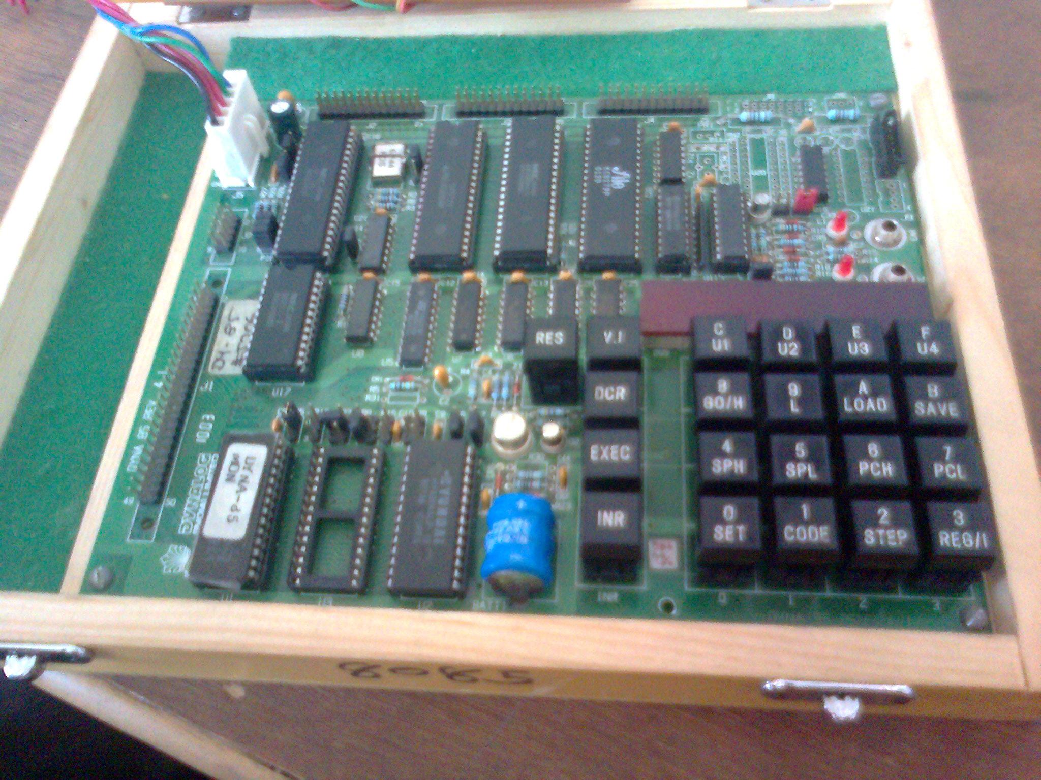
This Project traffic controller is made using microprocessor. In this project, to control traffic, 8085 KIT is used in which there are components, 8085 microprocessor, IC 8255(2Nos), ic8253 etc, J4/J5 female connectors of IC 8255 etc. Data gets transferred via FRC male connector, which is connected to J4 or J5. It has 26 pins.