

Full and Half wave rectifier filter circuit Electrical Project and Paper Presentations for Final Semester Degree and Diploma Engineering Students.
The rectifier converts the ac input voltage to a pulsating dc voltage There are two types of rectifier.
1.Half-wave rectifier
2.Full-wave rectifier
Half-wave rectifier
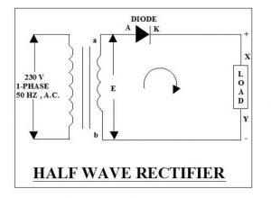
When a diode is connected to a source alternating voltage, it will be of alternately forward-biased, and then reverse-biased, during each cycle of the AC sine-wave. When a single diode is used in a rectifier circuit, current will flow through the circuit only during one-half of the input voltage cycle. For this reason, this rectifier circuit is called a half-wave rectifier. The output of a half-wave rectifier circuit is pulsating DC.
Half wave rectifier circuit is shown in figure and the waveforms of the input and output are shown in
Full-wave rectifier
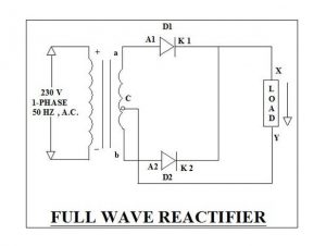
Full wave also know as Bridge Rectifier, for both Positive and negative swing or half duty cycle of the current there is a forward path through the Diode bridge. At the same time that one set of diodes is forward biased, the other set is reverse biased, In a bridge type rectifier circuit two diodes are At this point is in use, full wave circuit is compose of two half wave rectifier circuit Joined or fastened together to a single load.
Current flow Explain During the positive half duty cycle D2 and D3is on state, both D2 and D3 are in forward bias, D2 and D3 gates are open, D2 passing the positive arc duty cycle, while D3 is passing the negative arc duty cycle, During in this state D1 and D4 are at reverse bias and at off state.
Download Full and Half wave rectifier filter circuit Electrical Project here
[sociallocker id=60]Full and Half wave rectifier filter circuit Electrical Project[/sociallocker]
Leave a Reply